

Underfloor Radiant Cooling: Using Floor Circuits to Cool in Summer
Most homeowners think of underfloor heating as a winter solution. The same pipe network buried in a concrete screed, however, can double as a cooling surface when the seasons turn. By routing chilled water at roughly 16–20 °C through the existing floor circuit, the entire floor becomes a large radiant panel that absorbs heat from the room and leaves the air feeling noticeably cooler. This approach, called radiant floor cooling, is gaining ground in commercial buildings, new housing and renovation projects across Europe and Asia.
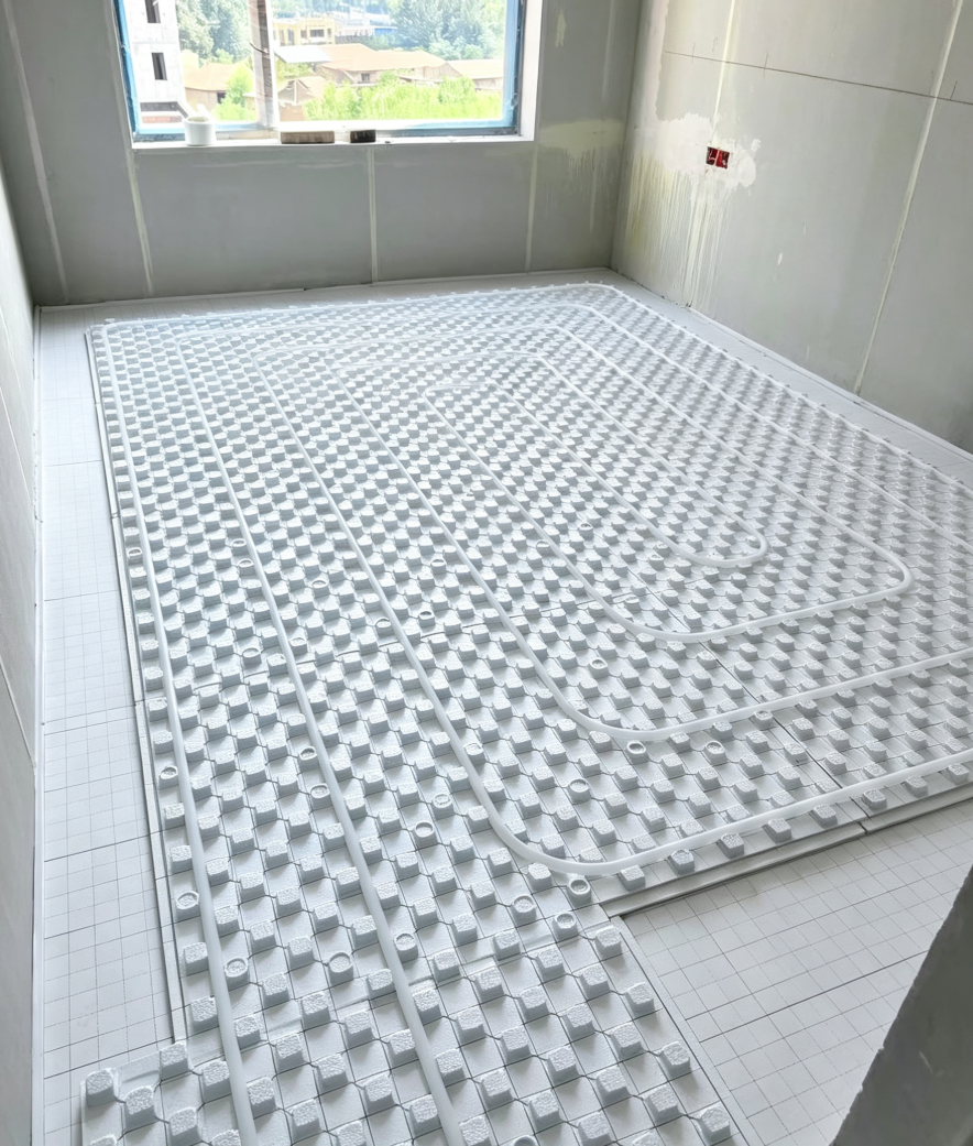
How Radiant Floor Cooling Works
In heating mode, warm water flows through the pipes and raises the floor surface to a comfortable temperature. Cooling reverses that energy transfer: chilled water at around 16–20 °C circulates through the same circuit and the floor surface drops below the room air temperature. Heat radiates from occupants, furniture and walls toward the cooler floor, while air near the floor cools, sinks gently and carries heat away in a slow, barely perceptible circulation. The room loses heat steadily and silently, with none of the blasts of cold air that conventional systems produce.
Why Radiant Cooling Feels Different from Air Conditioning
Traditional air conditioning chills air directly and relies on a fan to distribute it, which can create uneven temperatures and a familiar hum. Radiant floor cooling works indirectly: heat leaves the body and the room by radiation and slow natural convection, the same way a cool lake feels refreshing on a hot afternoon. Because the floor surface holds a steady, mildly cool temperature, the sensation is consistent across the whole room rather than concentrated near a vent. Comfort research shows people accept a wider range of air temperatures when radiant surfaces handle part of the cooling load.
The Dew Point Problem: Why Physics Sets the Limit
Radiant floor cooling has one non-negotiable constraint: the floor surface must never drop below the dew point of the room air. When warm, humid indoor air meets a surface colder than its dew point, moisture condenses on the floor — a slipping hazard and a breeding ground for mould. Preventing condensation is the single most important design rule for any floor cooling system.
In practice, supply temperature and the resulting floor surface temperature are controlled against indoor humidity. A thermostat with a humidity sensor feeds data to the controller, which raises the supply temperature automatically when humidity climbs. In very humid climates the supply setpoint may need to stay above 18 °C or even 20 °C to keep the surface safe. That is not a system flaw; it is a physical limit that responsible manufacturers and installers design around.
Cooling Output: What to Expect from the Floor
Radiant floor cooling is not a substitute for high-capacity air conditioning in a tropical climate. Depending on the floor finish and the temperature difference available, a well-designed floor circuit delivers roughly 40–70 W per square metre, while a fan coil unit can push several hundred. Floor cooling therefore works best in well-insulated buildings with moderate loads, or as a complementary system that shaves the peak and lets conventional cooling run less often.
In European-style buildings with good envelopes and solar shading, radiant cooling often covers the whole summer load on its own. In hotter regions, designers size the circuit to cut the hours of air conditioning needed each day, lowering energy use and improving comfort.
Floor Finishes and Their Effect on Cooling Performance
The covering over the pipe dictates how much cooling the system can deliver. Tile and stone conduct heat well, letting the cool surface reach the room with minimal resistance; polished concrete and large-format ceramic feel noticeably cooler than timber or thick carpet, which insulate the pipe and slow heat transfer. That does not make timber and carpet unusable — it means the design must account for reduced output, with pipe spacing and supply temperature adjusted for each finish.
Changeover Systems and Smart Controls
Switching a manifold from heating to cooling requires a changeover valve or a dual-mode controller. In its simplest form the valve redirects water from the boiler circuit to the chiller at the manifold; more advanced systems respond automatically to outdoor temperature, room temperature and humidity, raising the supply temperature when condensation risk rises. Commissioning matters as much as installation: the installer verifies that dew point protection is active and the humidity sensor reads accurately. Building management systems can integrate floor cooling with other plant, pre-cooling in the morning and coasting through the afternoon on stored coolth.
Insulation and Condensation Risk
Insulation under the pipe matters in both directions. In winter it stops heat escaping downward into the slab or the ground; in cooling mode the same layer stops the screed and structural slab from being chilled below pipe level. A chilled structural slab can condense moisture from the surrounding air, creating hidden problems that damage the building fabric over time. Boards with low thermal conductivity, together with pipe clips that hold exact spacing, give uniform surface temperatures and predictable output across the whole floor.
How a Manufacturer Supports Combined Heating and Cooling Projects
Hebei Huinuanjia Thermal Insulation Materials Co., Ltd. supplies insulation boards, pipe-fixing systems and manifold accessories designed for dual-mode radiant systems — low-profile panels, clips that keep correct spacing, and manifold kits that integrate with changeover controls. Buying the key hardware from one factory simplifies procurement, guarantees component compatibility and gives the installation team a clear specification. Projects that heat and cool through one floor circuit benefit most from a coordinated approach to insulation and pipe layout, which is exactly what a factory-focused supplier provides.
References
EN 1264-5:2008. Water based surface embedded heating and cooling systems — Part 5: Heating and cooling surfaces embedded in floors, ceilings and walls — Determination of the thermal output. CEN.
ASHRAE Handbook — HVAC Systems and Equipment. Radiant heating and cooling chapter. ASHRAE, Atlanta.
BS EN ISO 7730:2005. Ergonomics of the thermal environment — Analytical determination and interpretation of thermal comfort. BSI.